Your RC car sits lifeless on the workbench, its original remote long lost or broken. Commercial replacements cost nearly as much as the car itself, and generic controllers never feel quite right in your hands. What if you could build a custom remote that perfectly matches your grip, includes exactly the controls you need, and works flawlessly with your specific vehicle? Thousands of hobbyists have successfully created tailored RC remotes using accessible components and basic electronics skills. This guide reveals the practical steps to build your own functional remote from scratch, including critical safety considerations and troubleshooting tips most tutorials omit. You’ll learn how to match frequencies, design ergonomic layouts, and avoid the #1 mistake that causes signal interference—saving you hours of frustration.
Required Components for RC Remote Construction

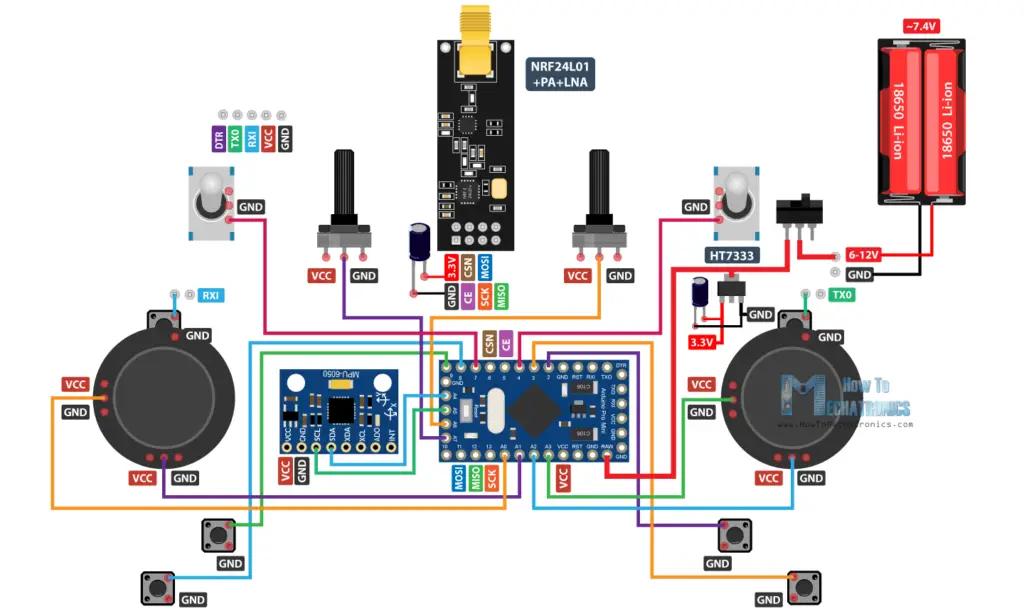
Before touching a soldering iron, gather these essential parts. Never skip component verification—using incorrect frequencies can damage your receiver. For most modern hobby-grade RC cars, you’ll need:
- 2.4GHz RF transmitter module (like nRF24L01+ or FS-iA6B)
- Microcontroller board (Arduino Nano or ESP32 recommended)
- Control inputs: Two analog joysticks (for throttle/steering) or momentary switches
- Power source: 2S LiPo battery (7.4V) with JST connector
- Housing material: 3D-printed case or sturdy plastic project box
- Signal verification tools: Multimeter and oscilloscope (optional but recommended)
Pro Tip: Match your transmitter’s protocol to your car’s receiver. Most modern systems use DSMX, FHSS, or FASST protocols—check your RC car’s manual before buying components.
Why Frequency Mismatch Causes Permanent Damage
Using a 27MHz transmitter with a 2.4GHz receiver isn’t just ineffective—it can fry your car’s electronics. The higher-frequency pulses overwhelm the receiver’s circuitry, melting sensitive components. Always confirm your RC car’s operating frequency:
– Toy-grade cars: Typically 27MHz or 49MHz (check label under battery compartment)
– Hobby-grade cars: Almost exclusively 2.4GHz since 2010
– Vintage models: May use 72MHz (airplane band)
Critical Warning: Never power on mismatched systems. Test signal compatibility with a multimeter first by checking voltage output at the receiver’s signal pin during transmission.
Building the Circuit: Step-by-Step Assembly
Connecting Control Inputs to Microcontroller
- Wire joysticks to analog pins: Connect throttle joystick VRx to A0, VRy to A1; steering to A2/A3
- Add pull-down resistors: Solder 10kΩ resistors between each signal pin and ground to prevent signal drift
- Power management: Connect battery positive to microcontroller’s VIN, negative to GND (include 100µF capacitor across power lines)
- Transmitter integration: Link nRF24L01+ CE to pin 9, CSN to pin 10, SCK to 13, MOSI to 11, MISO to 12
Common Mistake: Skipping pull-down resistors causes “ghost inputs” where the car moves randomly. Test with multimeter—idle signal should read 0V, not floating between 0.5-2V.
Programming the Transmitter Firmware
Upload this critical code sequence to your Arduino (using Arduino IDE):
“`cpp
include
include
RF24 radio(9,10); // CE, CSN pins
const byte address[6] = “00001”;
void setup() {
radio.begin();
radio.openWritingPipe(address);
radio.setPALevel(RF24_PA_MIN);
radio.stopListening();
}
void loop() {
int throttle = analogRead(A0);
int steering = analogRead(A2);
radio.write(&throttle, sizeof(throttle));
radio.write(&steering, sizeof(steering));
delay(20); // 50Hz transmission rate
}
“`
Key Adjustment: Modify setPALevel based on range needs:
– RF24_PA_MIN = 10 meters (indoor use)
– RF24_PA_MAX = 100+ meters (outdoor)
Exceeding range causes signal dropouts—test incrementally.
Pairing Your Custom Remote with the RC Car
Receiver Configuration Protocol
- Enter bind mode: Power on car receiver while holding bind button (usually 5+ seconds until LED blinks rapidly)
- Initiate pairing: Power on your custom remote—the transmitter automatically sends bind signal
- Verify sync: Solid LED on receiver = successful pairing (flashing = protocol mismatch)
Troubleshooting Tip: If pairing fails, check these in order:
1. Transmitter protocol matches receiver (DSMX vs. FASST)
2. Battery voltage > 7.0V (low voltage causes bind failures)
3. No metal objects within 12 inches of antennas during pairing
Signal Verification Without Specialized Tools
Use your RC car itself as a diagnostic tool:
– Throttle response test: Gradually increase throttle—car should move smoothly without stuttering
– Steering dead zone check: Joystick must return to exact center when released (no drift)
– Range test: Walk backward while operating car—signal drops at consistent distance indicate antenna issues
Critical Check: Run car at 50% throttle for 2 minutes. If receiver gets hot (>40°C), immediately power off—this indicates impedance mismatch damaging components.
Safety Protocols for DIY RC Remotes

Electrical Hazard Prevention
- Always disconnect battery before modifying circuits
- Use insulated tools when working near powered systems
- Install thermal fuse on battery line (5A rating for 1/10 scale cars)
- Never leave charging LiPo batteries unattended
Real Consequence: A single short circuit during assembly can ignite LiPo batteries in under 3 seconds. Keep sand bucket nearby when testing.
Fail-Safe Implementation
Critical for preventing runaway cars:
1. Add radio.setRetries(15,15) to transmitter code for maximum signal attempts
2. Program receiver to default to “throttle=0, steering=center” after 500ms signal loss
3. Test fail-safe by walking out of range—the car must stop within 2 seconds
Pro Tip: Tape a small magnet to your remote’s kill switch. If the car goes haywire, hold magnet near receiver to trigger emergency cutoff.
Troubleshooting Signal Interference Issues
Diagnosing Common Problems
| Symptom | Likely Cause | Fix |
|---|---|---|
| Car jerks erratically | Power supply ripple | Add 100µF capacitor across battery |
| Intermittent connection | Antenna obstruction | Extend antenna outside housing |
| Delayed response | Low transmission rate | Reduce delay() to 10ms |
| Complete signal loss | Frequency conflict | Change channel in code |
Eliminating 2.4GHz Interference
Modern environments are saturated with 2.4GHz signals (Wi-Fi, Bluetooth). Combat this by:
– Operating on channel 1 or 13 (least used by Wi-Fi)
– Using directional antennas (Yagi type) focused on car
– Avoiding concrete structures which reflect signals causing multipath interference
Field Test: Walk 30 feet from car while operating. If signal drops only when turning away, your antenna orientation is incorrect—reposition vertically.
Customization: Ergonomics and Advanced Features
Designing Comfortable Grips
Measure your hand:
– Thumb position: Place steering control where thumb naturally rests when gripping
– Trigger placement: Throttle should require 15-20% pressure to activate (prevents accidental acceleration)
– Weight distribution: Add metal washers to bottom half for balanced feel
Pro Builder Trick: Make temporary grips from moldable thermoplastic (e.g., Polymorph). Heat in hot water, shape around your hand, and use as template for final housing.
Adding Professional Features
Elevate your remote with these upgrades:
– Vibration feedback: Integrate ERM motor to signal low battery
– Telemetry display: Small OLED showing car speed/battery
– Mode switch: Toggle between racing (linear response) and crawling (exponential curve)
Code Snippet for Exponential Steering:
cpp

float expCurve = 1.5; // Higher = more sensitive center

steering = (steering > 512) ? 512 + (steering-512)*expCurve : 512 - (512-steering)*expCurve;
Maintenance and Longevity Tips
Preventing Common Failures
- Monthly: Clean joystick ports with compressed air (dust causes drift)
- After 10 uses: Check solder joints for cracks (thermal cycling weakens connections)
- Before storage: Discharge battery to 50% capacity (prolongs LiPo life)
Critical Habit: Always power off transmitter before receiver. Reverse sequence causes voltage spikes that degrade RF modules.
When to Abandon DIY for Commercial Solutions
Stop building if you encounter:
– Persistent signal dropouts after antenna/channel changes
– Receiver overheating during 1-minute operation test
– Inability to match your car’s protocol (some brands use proprietary encryption)
Smart Alternative: Buy a programmable transmitter like Flysky FS-i6X ($35). It supports 90% of RC cars and avoids DIY risks.
Building your own RC car remote delivers unmatched customization but demands technical precision. Focus first on frequency matching and fail-safe implementation—these prevent costly damage. Start with basic controls before adding telemetry displays, and always verify signal stability through systematic range testing. The most successful builders treat their first prototype as a learning tool, not a final product. When your custom remote powers up with a solid receiver LED and responds to your thumb’s subtlest movements, you’ll experience the unique satisfaction only creators know. Remember: Proper component selection prevents 90% of issues, and a multimeter is your most valuable tool for diagnosing the rest. For your next project, explore adding Bluetooth connectivity to log telemetry data—this guide gives you the foundation to innovate beyond commercial limitations.