When your RC car blasts down a straightaway and needs to slow for an upcoming turn, you instinctively pull back on the trigger—but have you ever wondered exactly how your remote control car brakes work? Understanding the mechanics behind RC braking systems is essential for any serious hobbyist who wants to maximize performance, improve lap times, and troubleshoot issues when stopping power diminishes. Whether you’re racing on a high-speed circuit or crawling over rocky terrain, your RC car’s braking system converts kinetic energy into controlled deceleration through sophisticated mechanisms that vary significantly based on vehicle type and application. This guide explains exactly how do RC car brakes work, breaking down electronic and mechanical systems so you can optimize your setup for any driving scenario.
RC car braking operates on the same fundamental principle as full-scale automotive brakes—converting kinetic energy into heat through friction—but implementation differs dramatically due to scale and power delivery. Most modern RC vehicles employ either electronic braking through the speed controller, mechanical friction systems applied directly to the drivetrain, or a combination of both approaches. Each method offers distinct advantages, and knowing how these systems function allows you to make informed decisions about maintenance, upgrades, and performance tuning. When properly configured, your RC car’s brakes provide not just stopping power but precise speed management that transforms handling characteristics and enables advanced driving techniques.
Electronic Speed Controller Braking: How Motor Control Creates Stopping Power
Electronic braking represents the primary approach in modern brushless RC vehicles, where the ESC actively manages deceleration by reversing current flow through the motor. When you move the throttle trigger toward the brake position, the ESC transforms your motor into a generator that creates resistance against rotation. This regenerative braking process converts kinetic energy into electrical resistance, slowing the motor’s spin and subsequently the vehicle’s wheels. The precision of electronic control allows for adjustable brake intensity, with most ESCs offering multiple settings drivers can select based on track conditions.
The three primary electronic braking modes serve specific purposes in RC applications:
– Drag brake applies consistent moderate force when throttle is released, preventing free-rolling on inclines
– Punch brake delivers stronger initial braking when throttle is released—ideal for technical climbing
– Dynamic braking varies force based on throttle position, with more aggressive deceleration as trigger moves further into brake range
Pro tip: Competition-grade ESCs allow independent adjustment of each parameter, letting you fine-tune brake force percentage, response curve, and initial bite. For general driving, start with brake settings between 25-50%, while racing applications often require 75% or higher.
Mechanical Disc vs. Drum Brakes: Comparing RC Car Stopping Systems
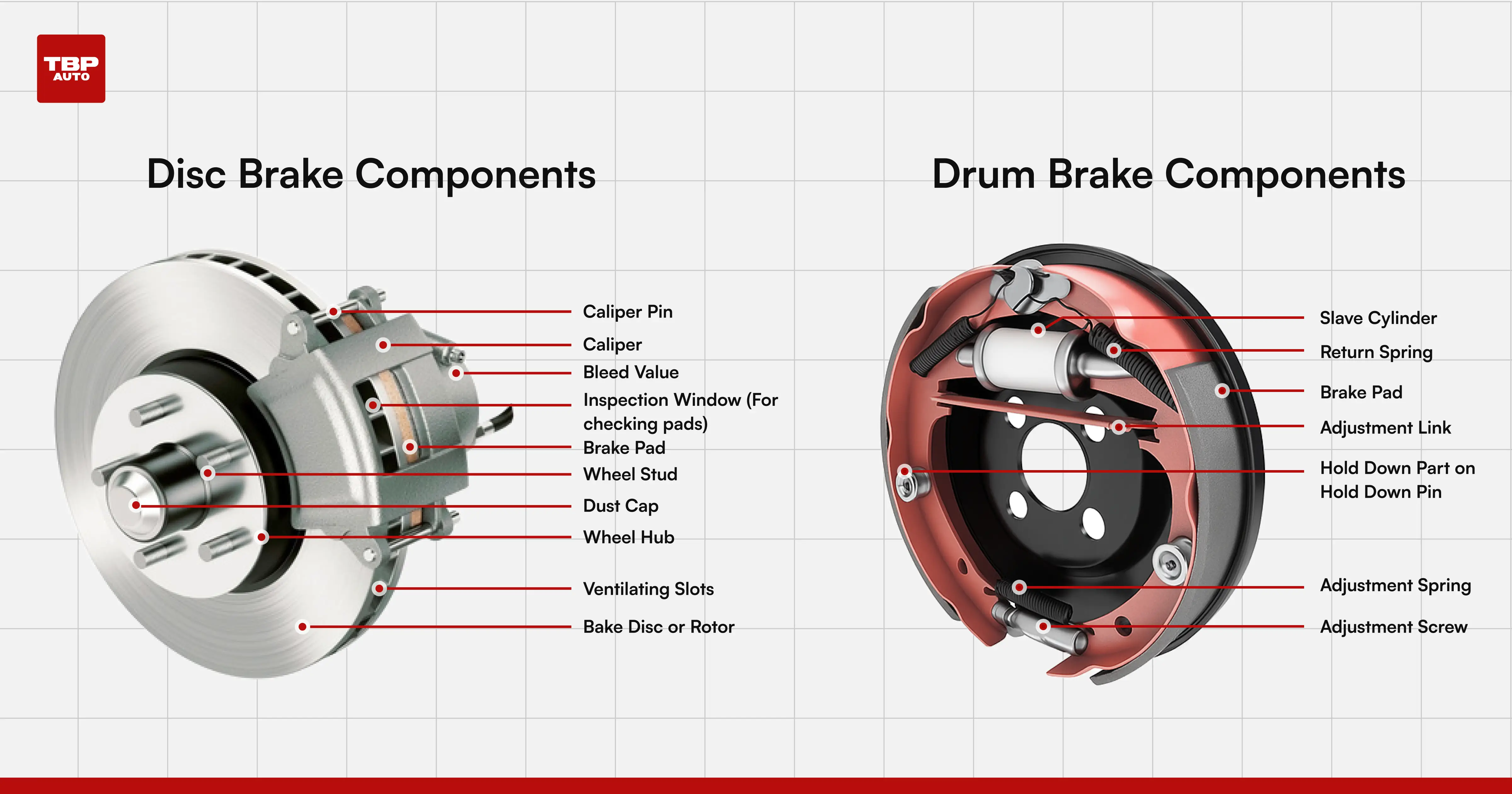
Mechanical disc brakes function similarly to bicycle systems, using calipers that squeeze pads against a rotating disc attached to the drivetrain. The disc typically mounts to the differential output shaft or wheel hubs. When you activate the brakes, a servo moves the caliper pistons, forcing friction material against the disc to create stopping force. This mechanical approach provides consistent braking regardless of motor RPM or battery voltage, unlike electronic braking which can vary with power supply conditions.
Drum brakes, while less common in performance applications, remain prevalent in entry-level vehicles. In this configuration, brake shoes expand outward inside a rotating drum when activated, creating friction against the drum’s inner surface. Drum designs provide strong initial braking force due to self-energizing shoe action but are more prone to brake fade during extended use. Critical difference: Disc systems offer superior cooling for repeated hard braking, while drum systems are simpler and cheaper but less suitable for high-performance applications.
Core Brake Components: What Makes Your RC Car Stop Reliably

The brake servo translates electronic signals into physical brake application, rotating its output arm when the transmitter trigger moves into brake position. This rotational movement connects through pushrods to the mechanical brake system. Servo selection significantly impacts performance—aggressive braking requires dedicated high-torque servos delivering at least 10 kg-cm of torque with response speeds under 0.10 seconds.
Brake discs come in various materials with distinct performance characteristics:
– Steel discs: Durable and cost-effective but heavier and prone to fade
– Aluminum alloy discs: Reduce rotating mass but wear faster
– Ceramic composite discs: Offer exceptional heat resistance for extreme applications
Brake pad material determines the coefficient of friction:
– Organic pads: Quiet operation with moderate friction for general use
– Semi-metallic pads: Higher friction for racing applications but increase disc wear
– Sintered metal pads: Highest friction for extreme use but require careful break-in
The Physics Behind RC Braking: Energy Conversion Explained
Every moving RC car possesses kinetic energy proportional to its mass and the square of its velocity (KE = ½mv²). When braking occurs, this energy must be dissipated through drivetrain friction or electrical resistance. Crucial insight: A vehicle traveling at twice the speed carries four times the kinetic energy, meaning braking distance increases dramatically with speed—a critical factor for high-speed racing.
During braking, inertial forces transfer the car’s weight forward, increasing load on front wheels while reducing rear wheel load. This weight transfer affects braking performance because friction force is proportional to normal force—the more weight pressing on a wheel, the more braking force it can generate before locking. Understanding this dynamic allows optimization of brake bias, the proportion of total braking force distributed between front and rear wheels.
Programming Your ESC Brakes: Step-by-Step Setup Guide
Most ESCs provide fundamental brake force adjustment expressed as a percentage of maximum available braking. Zero percent means the vehicle coasts when throttle is released, while 100% provides maximum dynamic braking. Follow this sequence for optimal setup:
- Start with brake settings at 30% for general recreational driving
- Adjust throttle deadband to eliminate unwanted coasting or braking
- Fine-tune initial brake force for desired bite at beginning of application
- Set brake force ramp for smooth progression through braking range
- Configure drag brake for consistent coasting behavior when throttle is released
Common mistake: Setting initial brake force too high causes front wheel lock-up during corner entry. For racing applications, start with initial force at 60-70% before fine-tuning.
Mechanical Brake Tuning: Optimizing Linkage and Bias
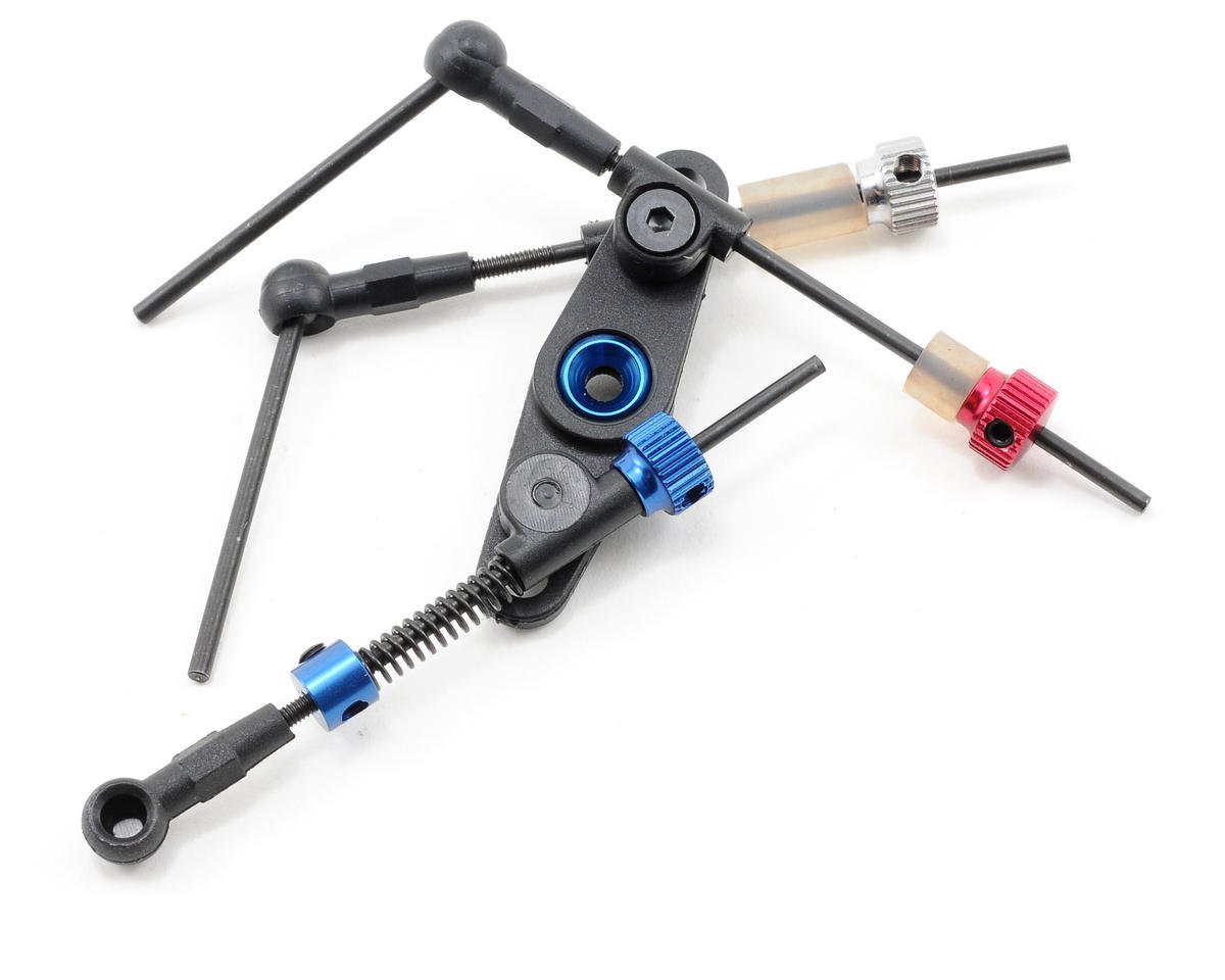
Proper linkage geometry ensures brake force application is linear and predictable throughout the servo’s range. When correctly adjusted, small throttle movements produce proportional brake force changes. Threaded pushrods allow fine adjustment of linkage length, compensating for pad wear and calibrating brake bite point—the throttle position where braking begins.
Brake bias adjustment optimizes front-to-rear force distribution:
– Forward-biased setups provide stronger initial braking but risk front wheel lock-up
– Rear-biased setups offer stability but sacrifice overall efficiency
– Optimal bias depends on vehicle weight distribution and tire characteristics
Visual cue: After bedding new pads, inspect pad contact pattern—uneven patterns indicate misalignment, warped discs, or contamination.
RC Brake Maintenance: When to Replace Pads and Discs
Routine brake inspection should occur before each driving session. Critical checks include:
– Pad thickness measurement at thinnest point (replace at 1-2mm remaining)
– Disc inspection for cracks, excessive wear, or warping
– Linkage integrity and servo operation verification
Common brake problems and solutions:
– Brake fade: Upgrade to higher-temperature pads or increase disc size
– Squealing: Address glazed pad surfaces or loose components
– Pulsation/judder: Check for warped discs or uneven pad contact
Replacement intervals: Pads typically need replacement before reaching 2mm thickness or every 10-15 race weekends for competition use.
Track-Ready Brake Optimization: Tire and Surface Considerations
Tire selection significantly impacts braking capability. Softer compounds provide more grip for aggressive braking but wear faster, while harder compounds last longer but require more brake force. Critical matching: Align brake settings with tire capabilities to prevent wasting braking capacity.
Track surfaces require different brake approaches:
– Tacky clay/carpet: Allows more aggressive brake force and later braking points
– Hard concrete/asphalt: Requires earlier application and gentler modulation
– Long straights + tight corners: Needs strong brakes resistant to repeated hard applications
Advanced technique: Trail braking—maintaining brake force into early corner turn-in—improves rotation and corner entry speed when brake bias is adjusted forward.
RC Brake Safety: Critical Checks Before Every Run
Electronic braking systems draw substantial current from batteries, creating potential hazards if connections are inadequate. Essential safety steps:
– Always disconnect battery before brake system maintenance
– Verify no drag when throttle is in neutral position
– Test brake function at low speed in controlled area before high-speed operation
– Check all brake hardware for cracks, deformation, or excessive wear
Warning: Brushless motor systems present electrical hazards—motor leads carry high voltage when armed, even without throttle input. Never arm the system with the vehicle supported where wheels could move unexpectedly.
Understanding how do RC car brakes work empowers you to maintain, troubleshoot, and optimize your vehicle’s stopping performance. Whether you rely on electronic braking through a programmable ESC, mechanical disc systems for tactile control, or a combination of both approaches, consistent inspection and proper configuration ensure reliable brake performance that keeps your RC car responding predictably in every driving scenario. By applying these principles, you’ll transform your RC experience from simple operation to precise control that maximizes both speed and safety.