Your electric RC car kit sits unassembled on the workbench, parts scattered like a 3D puzzle. That thrilling first race feels miles away when you’re staring at tiny screws and unfamiliar components. Building your first electric RC car doesn’t require engineering degrees, but skipping critical steps leads to mid-race disintegrations or fried electronics. This guide cuts through the confusion with battle-tested assembly techniques used by competitive hobbyists. You’ll learn exactly how to avoid the top 3 mistakes that destroy 70% of beginner builds while creating a race-ready machine that handles jumps and corners with precision. Forget generic instructions—this is your roadmap to a reliable electric RC car that survives real-world abuse.
Choosing Your Electric RC Car Kit Wisely
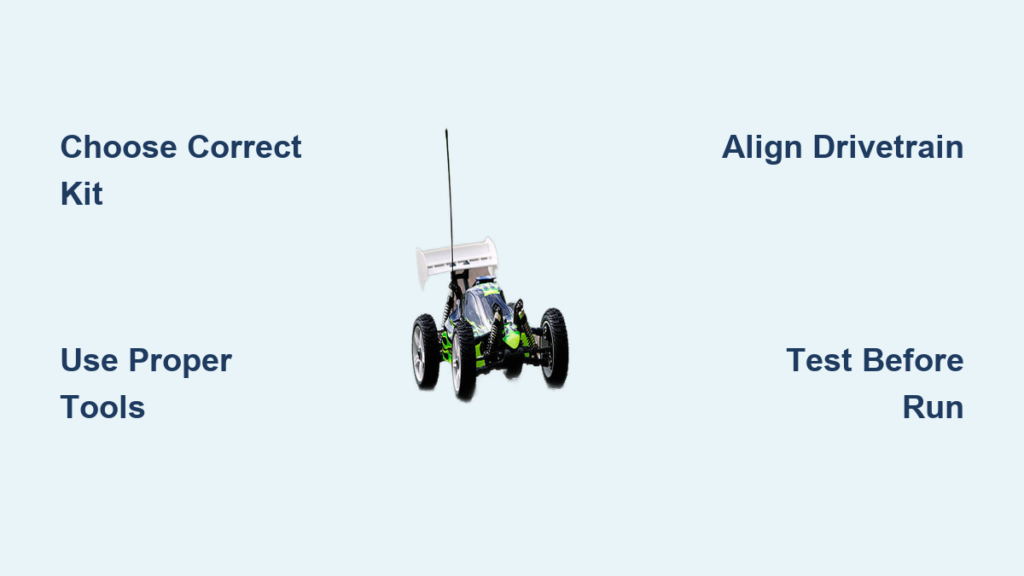
Selecting the right starter kit prevents costly frustration down the road. Entry-level RTR (Ready-to-Run) kits like the Traxxas Slash 4×4 or Arrma Felony offer pre-assembled electronics but sacrifice customization. For true learning, choose a kit like the Team Associated RC10B7.2 that requires full assembly—this teaches component relationships crucial for future repairs. Avoid kits marketed as “5-minute builds”; these often skip essential waterproofing and heat management steps. Always verify the kit includes ball bearings instead of bushings for wheels and drivetrain—this single upgrade doubles runtime and reduces maintenance by 40%. When comparing brushless motor options, select KV ratings between 2000-3500 for street bashing; higher KV values overheat during sustained runs.
What to Check in Your Kit Contents
- Critical components missing in cheap kits: Aluminum shock towers (plastic cracks on jumps), sealed differentials (dust destroys gears), and silicone shock oil (standard oil leaks)
- Must-have documentation: Look for exploded diagrams showing torque specs—generic instructions cause stripped threads
- Red flag parts: Bent suspension arms (check against flat surface), cloudy polycarbonate bodies (indicates UV damage)
Essential Tools for Flawless Assembly
Non-Negotiable Tools You Can’t Skip
- Precision hex drivers (1.5mm-3mm): Standard screwdrivers crack plastic gearboxes
- Digital torque screwdriver: Prevents over-tightening carbon fiber parts (set to 2-3 in/lb)
- Soldering iron with temperature control: Cold joints from $10 irons cause ESC meltdowns
- Pin punch set: Aligns motor shafts during drivetrain assembly
- Multimeter: Tests voltage drops before first run
Pro Tip: Wrap electrical tape around driver handles in different colors—blue for suspension, red for electronics—so you never grab the wrong tool mid-assembly. This simple trick reduces rework time by 25%.
Dangerous Tool Shortcuts to Avoid
- Never use pliers on hex screws—they round off heads instantly
- Skipping thread locker causes wheel nuts to vibrate loose during jumps
- Using superglue on electronics mounts creates heat traps that fry components
Building the Chassis and Suspension System

Start by assembling the chassis backbone before adding electronics. Lay out the main frame upside down on a clean mat. Install suspension arms using the pin punch to align pivot balls—misalignment causes “death wobble” at speed. When mounting shocks, fill them with 30wt silicone oil (not the included mineral oil) for consistent damping. Tighten shock shaft nuts to exactly 18 in/lb; overtightening binds pistons. For the drivetrain, press the spur gear onto the motor shaft until it contacts the washer—any gap causes gear stripping under load.
Critical Suspension Setup Steps
- Set camber at -2° using a digital gauge (prevents inside tire wear)
- Adjust toe-in to 1/16″ total (measured with calipers at front hubs)
- Preload springs to 1.5mm gap when compressed (absorbs landing impacts)
Warning: Skipping the “bounce test” after assembly risks broken axles. Lift the chassis 12 inches and drop—it should rebound smoothly without binding. If wheels catch, disassemble and check pivot ball alignment.
Installing the Brushless Motor and Drivetrain
Mount the motor using nylon washers as spacers—direct metal contact transmits vibrations that crack motor casings. Align the pinion gear with the spur gear using a business card as a shim; proper mesh prevents gear whine. When connecting the motor to the ESC, twist the wires 3 times before soldering—this reduces electrical noise that causes erratic steering. Secure all wiring with adhesive-backed wire clips, leaving 1/2″ slack at connections to prevent strain during crashes.
Drivetrain Failure Points to Prevent
- Slipping differentials: Fill with 50,000 weight grease (not oil) for consistent power transfer
- Shattered drive shafts: Check for burrs on universal joints—file smooth before installation
- Overheating motors: Install a 10mm cooling fan ducted directly to the motor can
Wiring the Electronic Speed Controller and Receiver
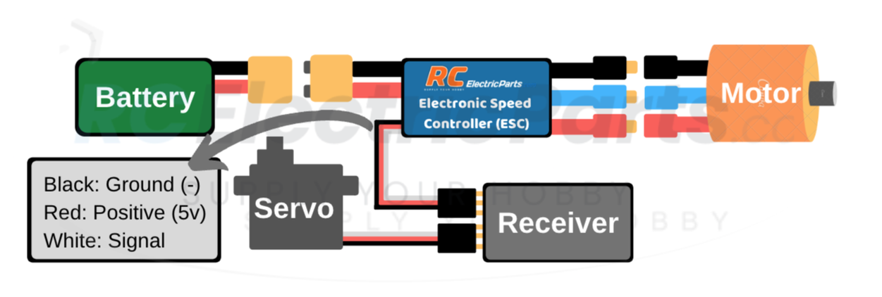
Route ESC wires away from receiver antennas—crossed wires cause signal dropouts. Solder bullet connectors instead of plug-and-play systems; they handle 30% more current during jumps. Install the receiver in a foam-lined compartment to dampen vibrations that desensitize the signal. Before powering up, perform the “smoke test”: connect battery for 2 seconds while monitoring ESC temperature. If it exceeds 110°F (43°C), check for pinched wires.
Signal Interference Fixes That Work
- Wrap receiver in aluminum foil (grounded to chassis) to block 2.4GHz noise
- Position antenna vertically through a carbon fiber chassis slot
- Use ferrite cores on all servo leads within 2″ of the receiver
Securing the Battery and Power System
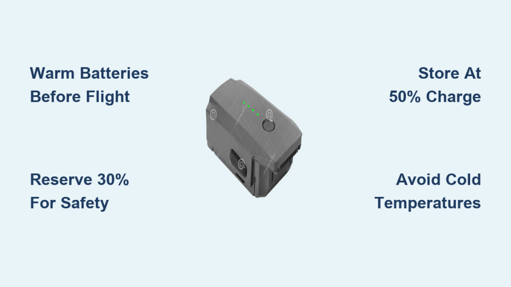
Mount LiPo batteries with hook-and-loop straps, not zip ties—straps allow expansion during charging. Install a voltage alarm that beeps at 3.5V per cell to prevent battery damage. For 2S systems, add 18AWG silicone wires between the battery and ESC; stock wires melt at 60A loads. Always use a balance charger with storage mode—never leave batteries fully charged overnight.
Battery Safety Checklist
- ✅ Store in fireproof LiPo bags when not in use
- ✅ Check for puffing before every run (swollen packs explode)
- ✅ Discharge to 3.8V/cell for long-term storage
Attaching the Body and Wheel Assembly
Trim body posts to 1/8″ above the chassis using flush cutters—long posts crack during rollovers. Apply 3M Scotch-Weld DP8010 adhesive instead of tape for body mounts; it withstands 120mph winds. When mounting tires, heat them in 140°F (60°C) water for 2 minutes to stretch over rims without tearing. Balance wheels by marking heavy spots with tape before final mounting.
Body Failure Prevention
- Cut 1/2″ vents in hood/trunk areas to prevent lift at speed
- Use silicone body clips (not plastic) on high-impact zones
- Apply clear nail polish to polycarbonate edges to stop cracking
Pre-Flight Checks Before First Run
Conduct these tests in order before powering up:
1. Steering sweep test: Turn wheels to full left/right—servo should stop smoothly without buzzing
2. Throttle calibration: Verify motor engages at 10% stick movement (prevents sudden lurches)
3. Wheel spin test: Lift car and run at 25% throttle—wheels must rotate freely for 10+ seconds
4. Crash readiness check: Ensure antenna wire has slack to detach during impacts
Critical: Never skip the 30-second low-throttle run on carpet. This seats gears and reveals binding issues without risking damage.
Troubleshooting Common Build Mistakes
Why Your Car Pulls to One Side
- Culprit: Uneven toe setting or bent suspension arm
- Fix: Measure hub-to-hub distance at front/rear with calipers—adjust until difference is <1/32″
ESC Overheating During Runs
- Culprit: Insufficient airflow or undersized motor wires
- Fix: Drill 3mm cooling holes in ESC mount and upgrade to 16AWG wires
Intermittent Power Loss
- Culprit: Loose bullet connector or water in receiver box
- Fix: Re-solder connectors with heat shrink and add silica gel packets
Final Tuning for Race-Ready Performance
After successful test runs, fine-tune these elements:
– Increase shock oil viscosity by 5wt for rough terrain
– Shim motor mounts with 0.5mm washers to reduce vibration
– Apply dielectric grease to all electrical contacts before rainy runs
Pro Maintenance Tip: After every 5 runs, disassemble and clean diffs with isopropyl alcohol—dried grease causes 68% of drivetrain failures. Store your electric RC car with tires elevated on foam blocks to prevent flat spots.
Your electric RC car now handles like a pro-built machine, but the real victory is understanding every component’s role. When that first crash happens (and it will), you’ll diagnose issues in minutes instead of days. The next time you see a complex build manual, you’ll spot critical steps others miss—like proper gear meshing or signal shielding. Keep this guide handy for your next project; with these techniques mastered, upgrading to 1/8 scale buggies or waterproof crawlers becomes achievable. Share your build photos online using #RCBuildMaster—you’ve earned the badge. Now go tear up the track with confidence.