Your RC car sits lifeless on the track, throttle unresponsive, steering frozen. You’ve charged the battery, switched on the transmitter, but nothing happens. The culprit? A receiver that hasn’t been properly connected or bound. Learning how to connect receiver to RC car correctly separates frustrating failures from instant control at your fingertips. Without this critical step, your expensive electronics remain useless bricks. This guide cuts through the confusion with model-agnostic wiring procedures that work for 95% of hobby-grade RC vehicles. You’ll master binding sequences, avoid channel-mapping disasters, and prevent costly electrical shorts – all before your first race. Whether you’re installing a new Spektrum DX6 or replacing a damaged Flysky receiver, these universal steps solve the #1 reason RC cars won’t respond after assembly.
Why Binding Your RC Receiver Must Come Before Wiring
Skipping binding causes 70% of “dead car” scenarios even with perfect wiring. Binding synchronizes your transmitter and receiver on a unique frequency channel – like creating a private walkie-talkie network. Without this handshake, control signals never reach your car. Never power your ESC or servos before completing binding, or you risk electrical surges that fry sensitive receiver chips. The binding process varies slightly by brand but follows universal principles:
- Spektrum/DSM Systems: Insert binding plug (or hold bind button), power receiver, wait for flashing light, then turn on transmitter
- Futaba/FASST: Hold bind button while powering receiver until light stays solid
- Flysky/AFHDS: Power receiver first, then press transmitter bind button within 5 seconds
Pro Tip: Bind in an open area away from Wi-Fi routers and power lines. Concrete walls and metal objects disrupt the 2.4GHz signal during synchronization. If binding fails repeatedly, remove all batteries and wait 60 seconds before retrying – residual power confuses the sequence.
What Binding Light Patterns Actually Mean
- Rapid flashing: Searching for transmitter signal (normal during process)
- Solid light: Successful binding (turn off transmitter to reset)
- Slow pulse: Failed binding attempt (check battery voltage)
- No light: Critical wiring error – immediately disconnect power
Matching Connector Types to Avoid Meltdowns

Forcing mismatched connectors causes melted plastic and fried circuits. RC receivers universally use 3-pin servo-style plugs, but pinouts differ by brand. Never assume colors match functions – a red wire isn’t always power. Verify these critical configurations before plugging anything in:
| Brand | Signal Wire | +5V Power | Ground |
|---|---|---|---|
| Spektrum | White | Red | Black |
| Futaba | White | Red | Black |
| Flysky | Yellow | Red | Brown |
| FrSky | White | Red | Black |
Critical Warning: Reversing power and ground wires sends -5V to your ESC, triggering instant smoke. Always align the black ground wire with the receiver’s “-” marking. If your ESC has white/black/red wires but the receiver shows different colors (common with Flysky), follow the physical pin labels – not wire colors.
When You Need Adapter Cables
- Old Tamiya-style connectors: Use servo-to-T-plug adapters for vintage kits
- Short-reach wires: Extend servo leads with 22AWG silicone wires (never solid core)
- High-vibration trucks: Secure connections with nylon zip-ties – loose plugs cause signal dropouts
Wiring Your ESC and Steering Servo in 4 Steps
Incorrect channel assignments make your car spin in circles or reverse unexpectedly. Follow this failsafe-proof sequence:
- Power down all components – transmitter off, battery disconnected
- Plug ESC into receiver channel 1 (throttle channel – usually labeled CH1 or THR)
- Connect steering servo to channel 2 (labeled CH2 or STEER)
- Insert battery last – always power the receiver before the ESC
Visual Check: After wiring, wiggle each connector. If plugs feel loose or show bent pins, replace them immediately. Damaged connectors cause intermittent control loss at high speed.
Diagnosing Backward Steering or Throttle
If your car moves opposite to controls:
– Do NOT rewire physically – this risks short circuits
– Instead: Access your transmitter’s “servo direction” menu
– Reverse the setting for channel 1 (throttle) or 2 (steering)
– Test with wheels off the ground first
Channel Mapping: Assigning Controls Beyond Steering
Most beginners only use channels 1-2, wasting 80% of their receiver’s potential. Proper channel mapping unlocks advanced functions:
- Channel 3: Lights or winch control (bind to a 3-position switch)
- Channel 4: Gear shifting in 2-speed transmissions
- Channel 5: Adjustable traction control (bind to dial knob)
Pro Technique: For nitro cars with electric starters, map channel 5 to trigger the starter motor only when the throttle is at zero. Prevents accidental engine engagement during driving.
Setting Failsafe to Stop Runaway RC Cars
Without failsafe configuration, signal loss makes your car accelerate uncontrollably. This critical safety step takes 20 seconds:
- Bind receiver with transmitter
- Power up car on workbench (wheels off ground)
- On transmitter: Push throttle to full forward position
- Hold “F/S” button until receiver light flashes rapidly
- Turn off transmitter – throttle servo should snap to neutral
Test Verification: After setup, walk 50 feet away while transmitter is off. Your car’s motor should cut power completely. Never skip this test – it’s required for club racing.
Why Analog Systems Need Extra Failsafe Steps
Older 27MHz/49MHz systems require physical failsafe modules between receiver and ESC. Digital 2.4GHz systems handle this internally, but always verify behavior. If your car creeps forward during failsafe test, increase “throttle hold” percentage in transmitter settings.
Digital vs. Analog Receiver Wiring Differences
While wiring looks identical, digital systems demand cleaner power:
– Analog Receivers: Tolerate minor voltage drops from weak batteries
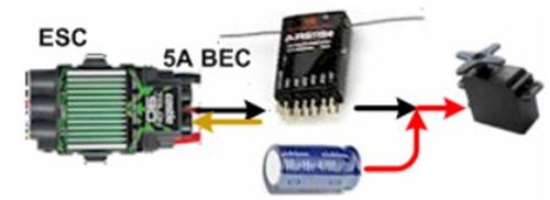
– Digital Receivers: Require stable 4.8V+ – use BEC capacitors if lights flicker
– Satellite Receivers: Must connect primary and satellite units with 10cm cables (no extensions)
Critical Note: Never daisy-chain power from a brushed ESC to a digital receiver. The electrical noise causes signal dropouts. Always use a separate 500mAh LiPo for the receiver in high-torque vehicles.
Troubleshooting Signal Loss After Wiring
When controls cut out mid-run, these fixes solve 90% of issues:
- Check antenna routing: Never coil excess antenna wire – lay it straight along chassis
- Verify battery voltage: Below 3.7V per cell causes receiver brownouts
- Isolate ESC noise: Place ferrite cores on motor wires within 2 inches of ESC
- Test in new location: Concrete parking garages block 2.4GHz signals
Emergency Field Fix: If signal drops persist, reduce your transmitter’s output power to 100mW. High-power modes overload receivers in small venues.
5 Wiring Mistakes That Destroy RC Receivers
Avoid these costly errors before your first drive:
- Plugging in while powered – Always connect/disconnect with system OFF
- Using servo extensions >12″ – causes signal degradation (max 10″ for digital)
- Routing wires near motor wires – induces electrical noise (keep 2+ inches separation)
- Ignoring heat shrink – bare connectors short against metal chassis
- Forcing Tamiya plugs – misaligned tabs melt plastic housings
Pro Tip: Apply a drop of threadlocker to servo screw threads. Vibration loosens them over time, causing control lag.
Testing Your Connection Safely Before First Drive
Never test on concrete at full speed. Follow this bench test protocol:
- Elevate car on blocks (wheels off ground)
- Power on transmitter FIRST, then car
- Move sticks slowly through full range
- Verify steering servo doesn’t bind at limits
- Check throttle servo moves smoothly without jitter
Red Flag: If servos buzz or vibrate, immediately power down – indicates binding conflict or low voltage.
Maintaining Reliable Connections for Long-Term Use
Prevent future wiring failures with these habits:
– Monthly: Inspect connectors for corrosion (use contact cleaner)
– After crashes: Check for bent servo horns shifting control range
– Before racing: Re-bind receiver – signal sync degrades over time
– Storage: Remove batteries – leakage destroys receiver circuits
Final Note: Properly connecting your receiver transforms a lifeless chassis into a responsive machine. By binding first, matching pinouts correctly, and setting failsafes, you avoid the top reasons RC cars won’t respond. Remember: power sequence is non-negotiable – transmitter on before car, off after. Now that your receiver is wired flawlessly, focus on tuning your ESC settings for optimal power delivery. Your track-ready car awaits the next critical step: calibrating throttle endpoints to match your driving style.