Your RC car sputters to a stop mid-race, leaving you stranded on the track with a fried commercial circuit board. Rather than waiting weeks for replacement parts or settling for generic performance, building your own custom circuit board puts you in control of every aspect of your vehicle’s responsiveness, power delivery, and reliability. This hands-on guide walks you through the exact process of designing, manufacturing, and programming a functional circuit board for your RC car, transforming you from a consumer of off-the-shelf electronics into a creator of custom solutions tailored to your specific vehicle and driving style. You’ll learn how to select the right components, design an effective PCB layout, assemble the board, and troubleshoot common issues—giving you the skills to optimize performance for speed, torque, or precision handling based on your racing needs.
Select Critical Components for Your RC Circuit Board
Choosing the right components establishes your RC car’s performance ceiling before you even begin soldering. Each element must work in harmony to deliver reliable power, precise control, and robust signal processing during high-stress operation.
Match ESC Specifications to Your Motor Type
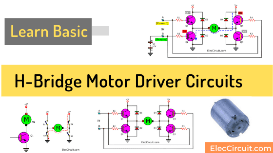
Your electronic speed controller (ESC) must precisely match your motor type and power requirements. For brushed motors, select an H-bridge controller like the L298N or TB6612FNG rated at least 20% above your motor’s maximum current draw—typically 20-30A for standard 1:10 scale vehicles. Brushless systems require a 3-phase ESC with six MOSFETs capable of handling your battery’s voltage range (7.4V-22.2V) and current demands (40-80A for competitive builds). Critical warning: Using an undersized ESC risks thermal runaway and permanent damage during high-load conditions. Verify your ESC’s PWM frequency (8-20kHz) ensures silent operation while providing smooth power delivery.
Position Radio Receiver for Maximum Signal Integrity
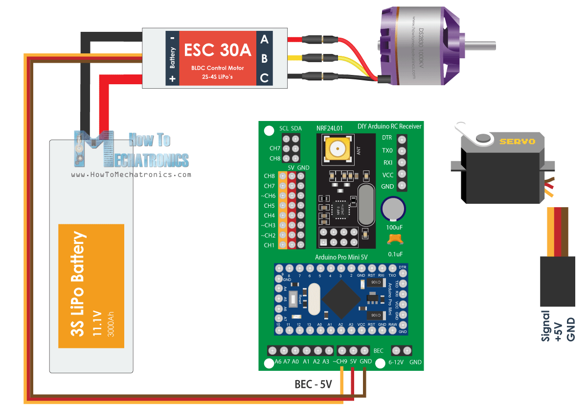
The 2.4GHz radio receiver processes your transmitter commands, making placement critical for reliable control. Choose a standard 4-6 channel receiver compatible with your transmitter protocol (Futaba, Spektrum, or FrSky). Mount the receiver away from high-current components like the ESC and motor—minimum 2 inches separation prevents electromagnetic interference from corrupting control signals. For optimal performance, position the receiver at the highest point on your chassis with the antenna oriented vertically. Use ferrite beads on receiver power leads to filter electrical noise that causes jittery steering response during acceleration.
Choose a Microcontroller Based on Processing Needs
Your microcontroller serves as the brain of the operation, with options ranging from beginner-friendly to advanced:
- Arduino Nano (16MHz): Ideal for basic brushed motor control with simple proportional algorithms
- STM32 Blue Pill (72MHz): Handles brushless systems with PID control and basic telemetry
- ESP32 (240MHz): Best for advanced features like Bluetooth configuration, sensor integration, and traction control
Pro tip: Select a microcontroller with at least 6 PWM output channels—4 for motor phases (brushless) or H-bridge control (brushed), 1 for steering servo, and 1 spare for future expansion. Verify the operating voltage matches your regulation circuit (3.3V or 5V) to prevent signal level mismatches.
Design Your PCB Layout for Maximum Reliability

An effective PCB layout prevents the most common RC circuit failures before they occur, addressing thermal management, signal integrity, and physical constraints of your vehicle’s chassis.
Calculate Trace Widths for High-Current Paths
Insufficient trace width causes overheating and voltage drops that cripple performance. For 1oz copper (standard for hobbyist boards), use these minimum widths:
- 10A: 2.5mm trace width
- 20A: 6mm trace width
- 30A: 10mm trace width
Critical step: Route motor power connections on outer layers with direct copper pours connecting to component pads. Add thermal relief patterns to high-current pads to prevent heat sinking during soldering. For ESC outputs, use polygon pours instead of single traces to maximize current capacity and heat dissipation.
Implement Proper Ground Plane Strategy
A continuous ground plane beneath all signal traces minimizes electromagnetic interference that causes control glitches. For mixed-signal designs combining digital and radio circuits, create separate ground planes connected at a single point (star topology) to prevent noise coupling. Key technique: Place thermal vias (5-10 per square inch) connecting ground planes on different layers to improve heat dissipation from power components. Keep ground connections for the receiver and microcontroller isolated from high-current return paths to maintain clean signal references.
Build Power and Control Circuits for RC Applications
Your power regulation and motor control circuits determine whether your RC car performs consistently or fails under load. Proper implementation prevents voltage drops that cause signal loss during critical moments.
Create a Dual-Rail Power System
Most RC cars require two voltage rails: 5V for servos/receivers and 3.3V/5V for the microcontroller. Replace inefficient linear regulators with buck DC-DC converters (85-95% efficiency) for both rails. Include these critical elements:
- 10μF ceramic + 100μF electrolytic capacitors on input/output
- Soft-start circuit to prevent inrush current spikes
- Reverse polarity protection via P-channel MOSFET
- Current sensing resistor (0.001-0.01 ohm) for monitoring
Testing tip: Measure voltage ripple under full load—exceeding 100mV indicates insufficient decoupling that causes microcontroller resets during acceleration.
Wire Motor Control Circuits Correctly
For brushed motors, construct an H-bridge with shoot-through protection that prevents simultaneous conduction of high-side and low-side MOSFETs. For brushless systems, implement a 3-phase bridge with gate drivers like the IR2104 providing proper high-side switching. Critical step: Add flyback diodes across motor terminals to dissipate inductive spikes that damage MOSFETs during commutation. Verify your gate drive signals have appropriate dead time (200-500ns) to prevent cross-conduction failures.
Program the Microcontroller for Precise Vehicle Control
Firmware transforms your hardware into a responsive RC system, with programming approaches varying based on your microcontroller choice and desired features.
Configure PWM Signal Processing
Your microcontroller must accurately measure incoming PWM signals from the receiver (typically 1000-2000μs pulse width). Use input capture hardware rather than software timing for precise measurement independent of processor load. Implement these critical routines:
- Signal validation: Ignore pulses outside 800-2200μs range
- Fail-safe detection: Trigger safe mode after 250ms signal loss
- Calibration storage: Save min/max/center values in non-volatile memory
Pro tip: Add a software low-pass filter to steering inputs to eliminate high-frequency noise causing twitchy handling—start with a 50ms time constant and adjust based on vehicle response.
Implement Control Algorithms for Smooth Operation
Simple proportional control maps input directly to output, but PID control provides superior response. For your first build, start with these base PID values:
- Throttle: P=0.5, I=0.05, D=0.1
- Steering: P=0.3, I=0.02, D=0.05
Troubleshooting note: Oscillation indicates excessive P gain; sluggish response suggests insufficient P gain. Tune one parameter at a time while testing at low speeds in a controlled environment.
Test and Validate Your Custom RC Car Electronics
Systematic testing prevents damage during your first drive and identifies issues before they cause crashes during operation.
Verify Power System Performance First
Before connecting motors or servos, complete this power validation checklist:
- Measure regulated voltages with no load (5V ±5%, 3.3V ±3%)
- Check quiescent current (<50mA indicates no shorts)
- Test reverse polarity protection (no current flow when reversed)
- Verify voltage stability under load (ripple <100mV)
Critical test: Apply full throttle with wheels elevated while monitoring voltage at the receiver—drops below 4.5V cause signal loss and erratic behavior.
Conduct Progressive Vehicle Integration Testing
Follow this sequence before high-speed operation:
- Static tests with wheels elevated: Verify motor direction, steering response
- Fail-safe activation: Block signal to confirm braking/coasting response
- Low-speed track testing: Monitor temperature at ESC MOSFETs
- Gradual speed increase: Test at 25%, 50%, 75%, then 100% throttle
Safety note: Monitor ESC temperature during testing—exceeding 80°C indicates inadequate cooling or excessive current draw requiring design modifications.
Troubleshoot Common RC Circuit Board Failures
Even well-designed boards encounter issues during development. Systematic troubleshooting saves time and prevents component damage.
Diagnose Motor Control Problems
When your motor fails to respond:
- Verify ESC arming sequence (throttle low at power-up, then center)
- Check phase connections for correct sequencing (swap any two wires if needed)
- Measure phase voltages with oscilloscope during throttle input
- Confirm gate drive signals reach MOSFETs with proper timing
Common fix: Intermittent operation often stems from cold solder joints on high-current connections—reflow all motor terminal solder joints before disassembling other components.
Resolve Signal Interference Issues
Jittery steering or control loss during acceleration indicates signal integrity problems:
- Reposition receiver away from ESC/motor (minimum 2-inch separation)
- Add ferrite beads to servo and receiver power leads
- Check ground connections between receiver and main board
- Verify stable regulator output under servo load
Pro tip: If problems persist, isolate the receiver on a separate power circuit with dedicated regulator—servo current demands often cause voltage ripple affecting radio reception.
Finalize Your RC Circuit Board Design
Building a functional RC car circuit board requires balancing electrical performance, thermal management, and physical constraints of your vehicle. Start with a simple brushed motor design before advancing to brushless systems, allowing you to master fundamentals while minimizing troubleshooting complexity. Budget $40-80 for a mid-range build using quality components, with PCB fabrication adding $20-50 for prototype boards. The learning curve typically spans 2-3 months from concept through working prototype for first-time builders. Critical advice: Document your design decisions thoroughly—each modification provides valuable insight for future iterations. Engage with online communities like RC Groups for peer feedback during development. With systematic testing and incremental improvements, your custom circuit board will deliver performance tailored to your specific racing needs while providing deep understanding of the electronics controlling your RC vehicle.