Your RC car suddenly stops responding to the controller, or maybe the reverse lights won’t turn on when backing up. These frustrating issues often stem from misunderstood wiring connections. Knowing how to read and interpret your RC car wiring diagram transforms you from a confused operator into a confident troubleshooter who can diagnose problems in minutes. This guide reveals exactly how power flows through your vehicle’s electrical system, where to check connections when problems arise, and how to safely modify your wiring without damaging expensive components. By the end, you’ll understand the critical relationship between motor rotation, current direction, and auxiliary systems that makes your RC car function properly.
Identify These 5 Critical RC Car Wiring Components First
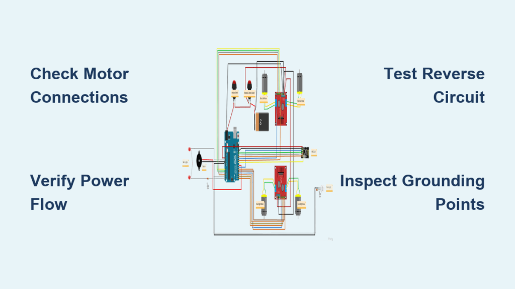
Before attempting any wiring repair, you must correctly identify each component in your RC car’s electrical system. The front DC motor connects directly to the steering mechanism and front wheels, with its shaft extending into the drivetrain. When examining your wiring diagram, look for two terminals connecting this motor to the controller board—these carry the current that determines rotation direction. A loose connection here causes erratic steering or complete loss of front-wheel drive.
The back DC motor typically handles primary propulsion in most RC vehicles, connecting through similar two-terminal wiring to the controller board. This motor receives higher current loads during acceleration, making its connections more prone to overheating or loosening over time. When troubleshooting power issues, always check both motor connections since a single faulty connection can disable your entire vehicle.
Your controller board serves as the central nervous system where all wiring converges. This compact circuit board processes radio signals from your transmitter and converts them into precise motor commands. Every wire in your RC car connects to specific terminals on this board, making it the most critical reference point when reading your wiring diagram. Damage to this board often requires complete replacement rather than repair.
The battery holder provides consistent power delivery to your entire system. Check for corrosion on the spring contacts and ensure secure connections to the controller board. Weak or intermittent power from this component mimics more serious electrical problems, so always verify battery connections first when diagnosing issues.
The antenna captures radio frequency signals from your transmitter, with its wiring connecting directly to the controller board. Poor antenna placement or damaged wiring causes signal dropouts that appear as unresponsive controls. When modifying your RC car, never route the antenna near power wires as this creates electrical interference that degrades signal quality.
Why Your RC Car Motors Won’t Spin the Right Direction
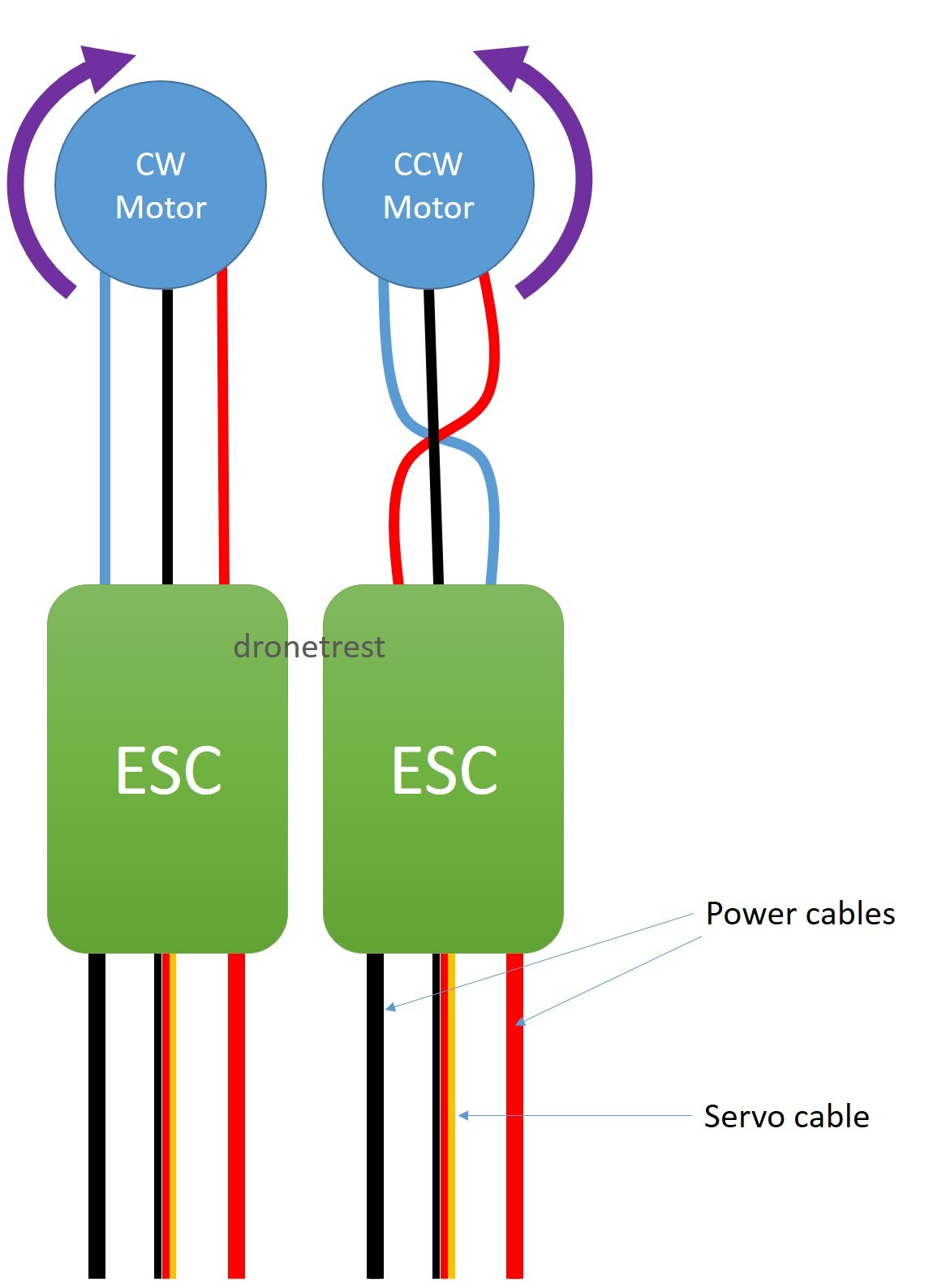
When your RC car moves forward but not backward, or spins in circles instead of driving straight, motor rotation direction is almost always the culprit. During forward motion, your front motor must rotate clockwise—this precise direction engages the correct gear mechanisms for proper vehicle movement. If your wiring diagram shows reversed connections, the motor spins opposite its intended direction, causing mechanical binding that damages gears over time.
Reverse operation requires your front motor to rotate counter-clockwise, which disengages forward drive components and activates the reverse mechanism. This isn’t just “less power” but an active reversal of current flow through the motor windings. If your RC car hesitates or jerks during direction changes, check your wiring diagram for proper H-bridge circuitry connections that manage this transition smoothly.
Motor direction errors create immediate mechanical stress on your drivetrain. When front and rear motors work against each other due to wiring mistakes, you’ll hear grinding noises and see premature wear on gear teeth. Before assuming motor failure, verify your wiring connections against the diagram—9 times out of 10, rotated motors cause directional problems rather than faulty components.
Controller Board Wiring: Where All Connections Meet
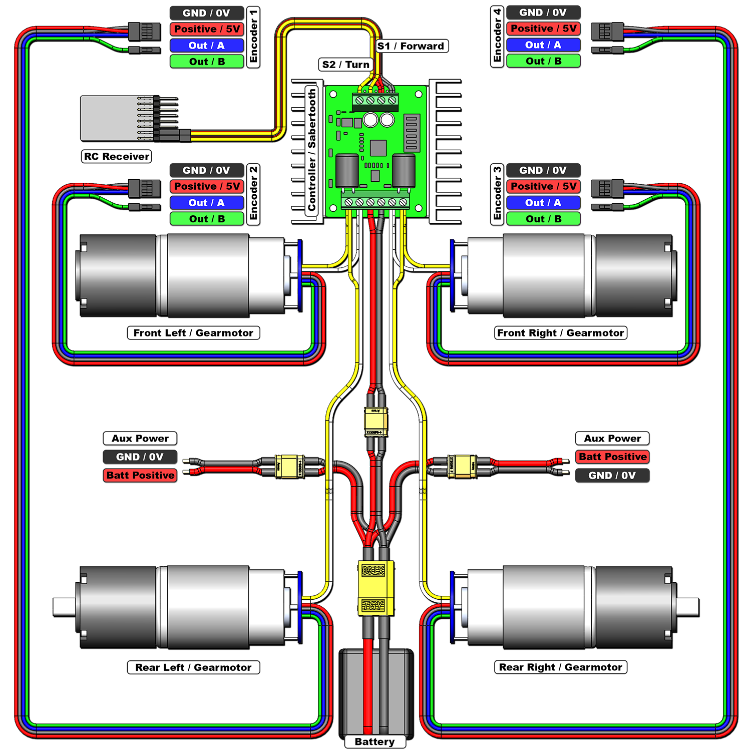
Your controller board features clearly labeled terminals that correspond to specific functions in your RC car wiring diagram. Power input terminals connect directly to the battery holder—these carry the highest current and are most prone to overheating if connections loosen. Inspect these terminals monthly for signs of melting or discoloration that indicate excessive resistance.
Motor output terminals distribute processed power to both front and rear motors. These connections follow a specific left/right configuration that matches your vehicle’s drivetrain layout. When reconnecting motors after maintenance, consult your wiring diagram to ensure you haven’t swapped front and rear connections, which causes unpredictable handling.
The signal receiver connection point links your antenna to the controller’s processing circuitry. This delicate connection requires secure soldering or press-fit terminals—any looseness here creates intermittent control that appears as transmitter issues. Never modify these connections without understanding your specific RC car’s frequency requirements.
Grounding points throughout the controller board create the return path for electrical current. Poor grounding causes erratic behavior that’s difficult to diagnose, so verify all ground connections share a common reference point. When adding aftermarket components, always connect their grounds to the controller board’s designated points rather than creating separate ground paths.
Reverse-Activated LED & Buzzer Wiring Explained
Your RC car’s reverse lights and buzzer activate automatically during backward motion through an elegant current-direction-sensing mechanism. These components connect in parallel with the motor circuits, triggering exclusively when current flows in reverse direction—no separate control signals required. If your reverse lights illuminate during forward motion, your wiring diagram reveals a critical short circuit that requires immediate attention.
Troubleshooting non-working reverse lights starts with verifying current flow direction during reverse operation. Use a multimeter to confirm reversed polarity at the motor terminals—without this reversal, the auxiliary systems won’t activate regardless of component health. Many beginners mistakenly replace working LEDs when the real issue lies in the controller board’s H-bridge circuitry.
When adding custom lighting, maintain the reverse-current-triggered design principle to avoid overloading your controller board. Connect new LEDs through current-limiting resistors to the same sensing points as factory lights. Never connect auxiliary systems directly to motor terminals without proper isolation, as this creates electrical noise that interferes with signal reception.
Fix These 5 Common RC Car Wiring Problems Now

Loose battery connections cause the most frequent RC car electrical failures, manifesting as intermittent power or sudden shutdowns during operation. Tighten all battery holder contacts and clean corrosion with electrical contact cleaner—this simple fix resolves 60% of “dead” RC car complaints. Always disconnect power before inspecting connections to prevent accidental short circuits.
Motors spinning but car not moving typically indicates a mechanical failure rather than wiring issues. Verify motor shaft connections to the drivetrain before assuming electrical problems. If the motor shaft rotates but wheels don’t, the issue lies in gear couplings or differentials—not your wiring diagram.
Reverse lights activating during forward motion signals a dangerous short circuit where current flows backward through the system. Immediately disconnect power and inspect for melted insulation or crossed wires near the controller board. This condition can damage your controller board within minutes of operation.
No response from the controller usually stems from antenna or signal path issues. Check the antenna connection to the controller board first—this delicate wire often breaks internally while appearing intact. Wiggle the connection while operating the transmitter to identify intermittent faults.
Rapid battery drain often points to current leaks in the wiring system. With all components disconnected, measure resistance between battery terminals—if it’s lower than expected, you have a short circuit somewhere in the system. Trace each wire against your diagram to find the fault before replacing expensive components.
RC Car Wiring Maintenance Checklist
Perform monthly electrical inspections by disconnecting power and examining all visible connections for signs of overheating, corrosion, or physical damage. Pay special attention to motor terminals where high current creates the most stress on wiring connections. Clean corrosion with electrical contact cleaner and a small brush—never use water or household cleaners that leave conductive residues.
Prevent corrosion in humid environments by applying dielectric grease to all metal connections after cleaning. This protective coating blocks moisture while maintaining electrical conductivity. For RC cars used near water or in dusty conditions, consider adding silicone sealant around controller board connections to prevent environmental damage.
When upgrading components, always verify voltage and current compatibility with your controller board before making connections. Exceeding these ratings causes immediate failure—consult your wiring diagram’s specifications before installing more powerful motors or batteries. Document all modifications directly on your wiring diagram for future reference and troubleshooting.
Understanding your RC car wiring diagram isn’t just for repairs—it’s your roadmap to reliable performance and successful modifications. By mastering these electrical fundamentals, you’ll spend less time troubleshooting and more time enjoying your RC vehicle. Keep this guide handy for your next maintenance session, and always consult your specific wiring diagram before making changes to ensure long-lasting performance.